| Looks Can Be Decieving Front view of the driver side strut rod and it's bushing assembly where they pass through the front of the sub-frame, the cross member. |
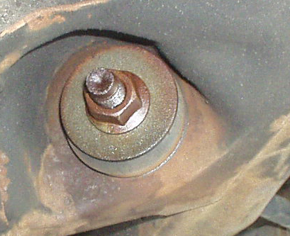 |
| Another view of the strut rod bushing as it protrudes from the front of the sub-frame. No indication of failure of the bushing cup or corrosion damage to the strut rod. Moisture is from liberal use of penetrating oil. | |
| Assembly Reference - o.e.m. I assembled all of the components onto the forward end of the strut rod after I removed it from the vehicle. I did this for people to use as an assembly reference, and also to show that there is no indication whatsoever that there is significant corrosion damage to the strut rod beneath these components. In fact, the condition of the exposed portion of the rod would lead you to believe that rust is not a factor at all. |
|
| The piece being held is the "cup" that recieves the front bushing. The ring to the right of the strut bar was once attached to the cup, forming a lip that allowed the cup to be crimped to the cross member. The detachment of this lip means the cup was no longer physically connected directly to the sub-frame. This allowed excessive motion at this end of the strut bar assembly, and all of the noise and steering issues associated with this problem. I chose not to weld the cup to the sub frame, but to use the Moog Problem Solver kit. Notice that even at this stage of dis-assembly, there is no apparent rust damage to the strut bar. |
|
| The rearmost of the front bushings was adhered to the washer behind it and to the strut bar. Both had to be removed in order to back the strut bar out of the sub-frame. Notice how much rust damage was concealed by the bushing assembly. Also, notice that the exposed portion of the strut bar gives no indication of the extent of the damage beneath. | |
| Notice the extent of the rust damage. A considerable amount of material is missing. The surface will be quite rough even after wire-brushing. I will replace this strut. | |
| Another viewof the bushing cup and the crimping ring that has separated. The ring would be visible at the front of the sub-frame. The cup is awkward to see from below or behind. These two pieces are replaced by the Moog Crossmember Repair Kit. | |
| The shiny part of the cup is the portion that projects to the rear of the cross member. The rusty portion is the part that is inserted into the cross member. | 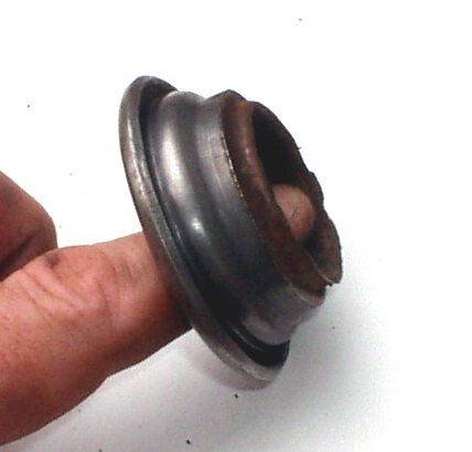 |
| I wanted to know if there was a difference between the projection of this cup and the projection of the Moog part. If there was significant difference I would need to compensate by adjusting the effective length of the new Strut Rod. |  |
| Measuring determined that there was less than 1.5mm difference. Ths meant I would set my new Strut Rod up to match the o.e.m. unit I was replacing. Any problems will be dealt with by the alignment shop - my first stop after final assembly. | 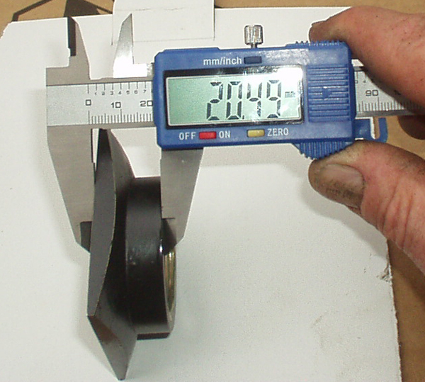 |
| Replacement Strut Rod: Spicer #6111078 The replacement Strut Rod is different from the original in many ways. I believe this is done so that one part can fit many vehicles. I was particuylarly concerned with the difference in the angles of the bends, but comparing them showed that the final offset was identical. I believe the greater angles of the new rod will cause it to be less stiff in tension and compression, but I don't know how noticeable it will be. Note the sleeves that slide onto the threaded section. These take the place of the corroded, machined sections on the original. I was concerned that they were loose on the rod, but a mechanic I respect explained why there was no worry. Email me if you want that explanation. |
|
| Use the supplied nuts to fix the effective length of the new rod. I didn't do any measuring, just matched the old and new. | |
Assembly Reference - new Note: |
|
| Get A Head Start I began the assembly by attaching the new LCA Moog #K8577 (left), and #K8579 (right). I decided to snug these pieces up before threading the rod through the sub frame because I could get better leverage. The LCA came with standard rubber bushings for the Strut Rod. I was lazy and burned the bushings out to replace with new TPR's, but I forgot to do this until after I had painted the LCA with POR-15. I figured I would need to paint it again, BUT the POR-15 was not damaged at all by the 8-10 minutes of flame exposure. Amazing stuff. After this, I greased the bushings for the front end and threaded the rod through the sub frame, adding the appropriate washer and bushing before threading the rod through the Moog kit. Then put the front bushing and washer in place and snug that end, muscle the LCA into its bracket on the sub frame and install its anchor bolt loosely. Only tighten this bolt when the suspension is loaded at rest. I put a jack under the hub and simulated the load that way. |
|
| Installation tip The boot for the LCA ball joint needs to be pressed onto the LCA prior to attaching the LCA to the Steering Knuckle. I found it impossible to do this by hand, so I used a C-clamp and a plumbing fitting I had on hand. A large socket will do the trick as well. |
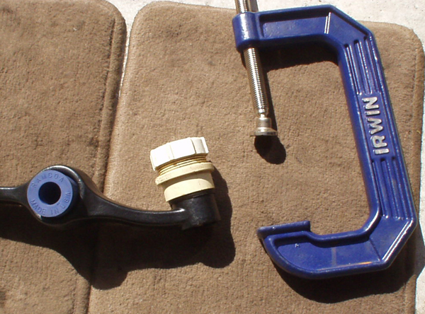 |
| The end result is a perfect fit. This plumbing fitting is called a 1-1/2" male adapter. I suggest taking your boot and LCA to the hardware store if you need to match it for size. | 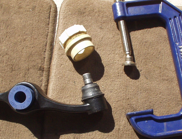 |
Questions? Comments? Email Me. |
|